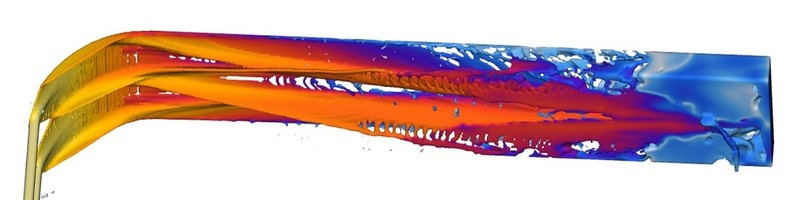
I wanted to share an update on the Bell Housing HPDC simulations from this week, shown here is our overflow and runner design, with locations of entrained air and fill, just before the whole casting cavity is full. Note the cavity air pressure is quite high and notably in regions not being vented. The intent next is to compare venting to air as shown here vs. vent through vacuum. Stay connected to see the next post comparing this with vacuum, I expect lot less entrained air! Quite a valuable insight through simulations...Happy weekend! #hpdc #metalcasting #diecasting #flow3dcast #flow3d #manufacturing #aluminum
I don't think that the gate area is enough to feed this volume. It's much needed to fill the casting instead
Keep in mind that the simulations do not accurately predict the gas pressure within the cavity due to vaporization of the release. This can be 10 times the gas pressure due to the original air within the cavity. My reaction is the same as Sukdeep Singh. The part is under gated an under vented.
does the simulation give you a one speed all the way from start to end or it provides the more accurate low and high-speed representation ?
Can die temp be considered in this simulation?
Using flow simulation for cavity fill will always be a continuous improvement route, initial concepts will change to improve each iteration. Most companies that produce aluminium hpdc have a history of similar parts and should develop and improve as a natural course, however the old saying of "it's been working for years why change" should be avoided. The goal these days is to provide acceptable parts by the most efficient way, simulation is the best way before cutting metal, to gauge cavity fill provided those viewing the graphics understand what is being shown.
Hello, i agree with Jan. For me the convergence criterion of the flow seems correct. Separate the two channels and a good track seen the distance from the injection site. Thought just like a river shaped like a trapeze and continues in curvature and tangency. For me the casting attack surface is directly related to the weight of the part and the theoretical flow of filling. The theoretical flow rate is directly related to the filling time of the cavity. For example: 15Kg in 0.07 sec => attack surface 1865mm² => vacuum attack surface 653mm²
I think if the position of the inlet gate is moved to the middle of the part, the injection quality will be greatly improved.Of course, simulation can help in this field.
Gate i fixed in the portion where liquid metal ha to fill larger section at the bottom. If the product permits it could have been on the opposite side.Jut a thought
Technicien bei FONDAREX SA
1yI think it is a good starting design, even do I have the same impression as Mr Singh and Spiller, the gate square section should be at least 30 % more. On the venting side using vacuum you’re quiet alright. If the simulation program gives the possibility to reduce the air pressure to 200 mbar, almost all air/gas porosity will be gone …. And in real casting as well if you do it right.