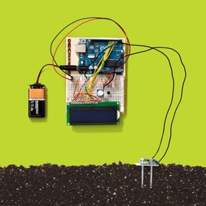
My perennials always died because I watered them too little or too much, or put them somewhere too dark or too hot. Recently I vowed to keep my plants alive, so I turned to Arduino. I'd been looking for an excuse to try out this microcontroller platform, which I knew could be programmed to do a lot of cool things. Why not use it to save my ailing amaryllis? In an afternoon I built a smart sensor that reads and displays soil-moisture levels, light intensity, and temperature.
What You'll Need
• Bolts, nuts, ring terminals ($5)
• Arduino Uno ($28) or Arduino Uno Starter Kit ($100), which includes the following parts:
• Solderless breadboard ($5)
• Assorted wires ($7)
• Thermistor ($2)
• Photoresistor ($1)
• 10K-ohm resistors ($8 per pack)
• Potentiometer ($1)
• LCD display ($10)
Getting Started
Arduino uses open-source hardware and software, so I was able to borrow ideas from other well-tested devices.
I found instructions for several Arduino-based plant sensors online, including the GardenBot, the ArduGarden, and a solar-powered sensor that measures soil fertility and weather conditions. The last was designed by Luke Iseman, the cofounder of Soil IQ, a company that makes devices primarily for urban farmers. In the end I took ideas from each to create something that suited my skill level and needs. My device has two soil probes that measure how much the soil resists the flow of electricity, which tells you how moist it is. Adding a photoresistor (light sensor) and a thermistor (temperature sensor) and connecting them to a programmed Arduino gave me a gadget that monitors the environment of a single plant.
You can buy all the parts separately for less than $70. However, I used the official Arduino Starter Kit ($100), which includes everything I needed, minus the nuts, bolts, wires, and ring terminals for making the soil probes.
Wiring the Hardware
Plant Sensor Diagram (PDF, 2.4MB, requires Adobe Reader)
I made the two soil probes using 5/16 x 2-inch full-thread steel bolts, 20-gauge wire, ring terminals to attach the wires to the bolts, and nuts to secure the ring terminals tightly against the bolt heads. To ensure the resistance measured between the probes was consistent, I cut a rectangle from an old plastic container, drilled two holes in it, and screwed in both bolts. That kept the probes the same distance apart with every use.
A solderless breadboard allowed me to experiment with the wiring as I worked. Several online guides, along with Arduino's project guidebook, provided schematics on how to wire the thermistor, photoresistor, and soil probes. I connected one soil probe to power, and the other to ground through a 10kΩ resistor and to Arduino's analog pin A0. I did the same with the thermistor and photoresistor, but connected those to pin A1 and pin A2, respectively.
I connected the LCD display according to a slightly modified design of Arduino's tutorial, with LCD VSS to ground, LCD VCC to power, LCD RS pin to digital pin 7, LCD Enable pin to digital pin 6, LCD D4 pin to digital pin 5, LCD D5 pin to digital pin 4, LCD D6 pin to digital pin 3, LCD D7 pin to digital pin 2, and LCD R/W pin to ground. And I attached a potentiometer, with an outer pin to the LCD VCC pin, the wiper (middle pin) to the LCD VO pin, an outer pin to the LCD R/W pin. (Twisting the potentiometer lets you turn the LCD screen on and off.)
Programming the Device
I borrowed most of the Arduino's programming code from Iseman's project and uploaded it to the Arduino (See Below). The LCD display showed moisture, temperature, and light readings in variable resistance values, so I needed to calibrate the data to understand what it all meant. To do that, I physically changed the conditions for each sensor to see how it affected the readings. For example, in bright light, my photoresistor had readings between 880 and 900, but when I covered the sensor with my finger, it read 530. My soil-moisture reading was in the low 700s in soil that had around 30 percent moisture (according to a comparison with a commercial soil-moisture sensor), and 661 in a drier pot. This gave me a good idea of how the readings related to the plant's environment.Of course, every plant has different watering and lighting needs, so I checked resources such as the National Gardening Association's plant-care guides to provide insight into the amaryllis on my desk. Now, with the sensor sitting right next to it, I feel much more optimistic about its survival.
Code:
#include
//initialize variables for sensor pins
int moistPin = 0;
int tempPin = 1;
int lightPin = 2;
//initialize variables to store readings from sensors
int moistVal = 0;
int tempVal = 0;
int lightVal = 0;
// initialize the library with the numbers of the interface pins
LiquidCrystal lcd(7, 6, 5, 4, 3, 2);
void setup()
{
//initialize the serial port
Serial.begin(9600);
// set up the LCD's number of columns and rows:
lcd.begin(16, 2);
}
void loop()
{
moistVal = analogRead(moistPin);
//display moisture reading on lcd
lcd.clear();
lcd.print("moisture ");
lcd.print(moistVal);
//wait 4 seconds
delay(4000);
//display moisture reading on lcd
tempVal = analogRead(tempPin);
lcd.clear();
lcd.print("temperature ");
lcd.print(tempVal);
delay(4000);
lightVal = analogRead(lightPin);
//display moisture reading on lcd
lcd.clear();
lcd.print("light ");
lcd.print(lightVal);
delay(4000);
}
Alexandra Chang is the author of Days of Distraction. She currently lives in Philadelphia.
