
ÍNDICE DE CONTEÚDO
- STM32F0DISCOVERY + LCD
- STM32F0Discovery + LCD + Bluetooth
Objetivo
O objetivo deste artigo é realizar uma comunicação wireless entre um setup controlado por uma STM32F0Discovery e um PC, o primeiro composto por um módulo Bluetooth HC-05 e o último por um HC-06.
Pré-requisitos
Para acompanhar este projeto, serão necessários:
- Conhecer o STM32CubeMX e o uVision 5;
- Entendimento de estrutura de dados e ponteiro de função em linguagem C.
Materiais
Materiais necessários:
- Um módulo Bluetooth HC-05 e um HC-06;
- O setup realizado no artigo anterior: STM32F0Discovery + LCD;
- Um conversor UART/USB;
- Cabos com conectores tipo fêmea.
Configurações de hardware
Como premissa, aproveitaremos o projeto do STM32CubeMX do artigo anterior para esta aplicação, assim abra o projeto citado e realize as seguintes configurações:
- No periférico USART2, modifique o estado de Mode para Asynchronous. Feito isto, verá que os pinos PA2 (USART2_TX) e PA3 (USAT2_RX) ficarão em “verde escuro” (visualizando a figura do microcontrolador);
- Assim, gere os arquivos necessários para o uVision 5.
Conexões dos hardwares
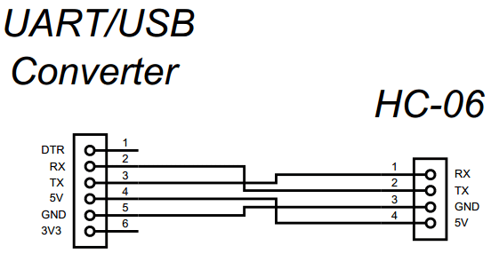
Antes de mais nada, o PC nesta aplicação funcionará como um slave device, ou seja, receberá mensagens (strings) da Discovery, assim o hardware para o device será:
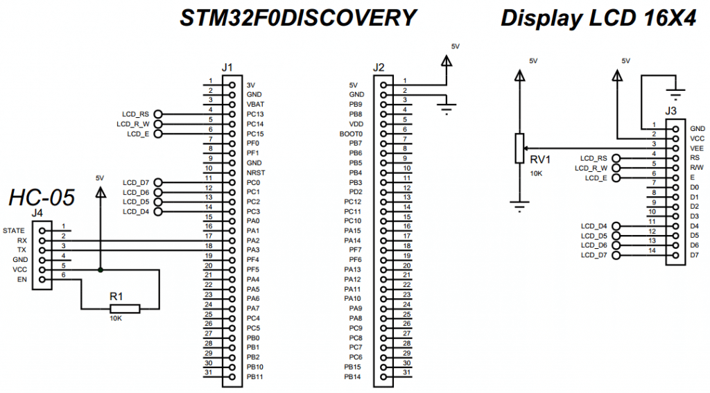
O esquema de conexão da Discovery é visto a seguir:
Código
Com o mesmo projeto (.uvprojx) do uVision 5 do artigo anterior, abra e realize a escrita do código a seguir:
|
1 2 3 4 5 6 7 8 9 10 11 12 13 14 15 16 17 18 19 20 21 22 23 24 25 26 27 28 29 30 31 32 33 34 35 36 37 38 39 40 41 42 43 44 45 46 47 48 49 50 51 52 53 54 55 56 57 58 59 60 61 62 63 64 65 66 67 68 69 70 71 72 73 74 75 76 77 78 79 80 81 82 83 84 85 86 87 88 89 90 91 92 93 94 95 96 97 98 99 100 101 102 103 104 105 106 107 108 109 110 111 112 113 114 115 116 117 118 119 120 121 122 123 124 125 126 127 128 129 130 131 132 133 134 135 136 137 138 139 140 141 142 143 144 145 146 147 148 149 150 151 152 153 154 155 156 157 158 159 160 161 162 163 164 165 166 167 168 169 170 171 172 173 174 175 176 177 178 179 180 181 182 183 184 185 186 187 188 189 190 191 192 193 194 195 196 197 198 199 200 201 202 203 204 205 206 207 208 209 210 211 212 213 214 215 216 217 218 219 220 221 222 223 224 225 226 227 228 229 230 231 232 233 234 235 236 237 238 239 240 241 242 243 244 245 246 247 248 249 250 251 252 253 254 255 256 257 258 259 260 261 262 263 264 265 266 267 |
/* Includes ------------------------------------------------------------------*/ #include "stm32f0xx_hal.h" /* USER CODE BEGIN Includes */ #include "LCD.h" #include "string.h" #include "stdio.h" /* USER CODE END Includes */ /* Private variables ---------------------------------------------------------*/ UART_HandleTypeDef huart2; /* USER CODE BEGIN PV */ /* Private variables ---------------------------------------------------------*/ #define NUM_FUNC_BT (unsigned char)4 #define INIT_CPLT_BT (unsigned char)7 #define RX_BUFFER_SIZE (unsigned char)10 #define _2s (unsigned int)2000 #define _4s (unsigned int)4000 enum { SendAt = 0, SetConfOrgl , SetUART , SetName , SetPswd , SetRole , SetCmode , InitBluetooth }; enum { SendCmdBt = 0, WaitCpltBt, NextBt , FinishBt }; uint8_t CmdAt1[] = {"AT\r\n"}; uint8_t CmdAt2[] = {"AT+ORGL\r\n"}; uint8_t CmdAt3[] = {"AT+UART=38400,0,0\r\n"}; uint8_t CmdAt4[] = {"AT+NAME=BTMASTER\r\n"}; uint8_t CmdAt5[] = {"AT+PSWD=1234\r\n"}; uint8_t CmdAt6[] = {"AT+ROLE=1\r\n"}; uint8_t CmdAt7[] = {"AT+CMODE=1\r\n"}; uint8_t CmdAt8[] = {"AT+INIT\r\n"}; typedef void(*pFunc)(void); pFunc pInitBt; typedef struct { uint8_t *pData[8]; uint8_t LengData[8]; uint8_t State; uint8_t Index; uint32_t TimeOut; pFunc pFuncBt[NUM_FUNC_BT]; }BT_TypeDef; BT_TypeDef BtData; uint8_t RxBuffer[RX_BUFFER_SIZE] = {0}; /* USER CODE END PV */ /* Private function prototypes -----------------------------------------------*/ void SystemClock_Config(void); static void MX_GPIO_Init(void); static void MX_USART2_UART_Init(void); /* USER CODE BEGIN PFP */ /* Private function prototypes -----------------------------------------------*/ void vSendCmdBt (void); void vWaitCpltBt (void); void vFinishBt (void); void vNextCommandBt (void); void vInitBlueTooth (BT_TypeDef* Bt); /* USER CODE END PFP */ /* USER CODE BEGIN 0 */ void vSendCmdBt(void) { HAL_UART_Transmit(&huart2, BtData.pData[BtData.Index], BtData.LengData[BtData.Index], 10); /* If the all command were sent and returning "OK", then FINISH the Bluetooth init.. */ if(BtData.Index >= INIT_CPLT_BT) { BtData.State = FinishBt; pInitBt = BtData.pFuncBt[BtData.State]; } else { /* Keep sendig AT commands */ BtData.State = WaitCpltBt; pInitBt = BtData.pFuncBt[BtData.State]; } } void vWaitCpltBt(void) { BtData.TimeOut = HAL_GetTick(); HAL_UART_Receive(&huart2, RxBuffer, RX_BUFFER_SIZE, 10); /* The return command is "OK", indicating that sent command was right */ if(RxBuffer[0] == 'O' && RxBuffer[1] == 'K') { BtData.TimeOut = 0; BtData.State = NextBt; pInitBt = BtData.pFuncBt[BtData.State]; } else { /* Timeout procedure */ if(BtData.TimeOut >= _4s) { LCD_Clear(); LCD_GoTo(0,1); LCD_SendText("BlueTooth Fail!"); LCD_GoTo(0,2); LCD_SendText("Reset the board!"); for(;;){} } /* Send another command to try stablish the comunication */ else if(BtData.TimeOut >= _2s) { BtData.State = SendCmdBt; pInitBt = BtData.pFuncBt[BtData.State]; } } } void vFinishBt(void) { return; /* Back to main */ } void vNextCommandBt(void) { uint8_t i; BtData.Index++; /* Clean the Buffer */ for(i = 0; i < sizeof(RxBuffer) / sizeof(uint8_t); i++) { RxBuffer[i] = 0; } BtData.State = SendCmdBt; pInitBt = BtData.pFuncBt[BtData.State]; } void vInitBlueTooth(BT_TypeDef* Bt) { if(Bt != NULL) { /* Load the pointer vector with the AT comand adresses */ Bt->pData[SendAt] = CmdAt1; Bt->pData[SetConfOrgl] = CmdAt2; Bt->pData[SetUART] = CmdAt3; Bt->pData[SetName] = CmdAt4; Bt->pData[SetPswd] = CmdAt5; Bt->pData[SetRole] = CmdAt6; Bt->pData[SetCmode] = CmdAt7; Bt->pData[InitBluetooth] = CmdAt8; /* inform the size of the contents pointed */ Bt->LengData[SendAt] = (sizeof(CmdAt1)/sizeof(uint8_t)) - 1; Bt->LengData[SetConfOrgl] = (sizeof(CmdAt2)/sizeof(uint8_t)) - 1; Bt->LengData[SetUART] = (sizeof(CmdAt3)/sizeof(uint8_t)) - 1; Bt->LengData[SetName] = (sizeof(CmdAt4)/sizeof(uint8_t)) - 1; Bt->LengData[SetPswd] = (sizeof(CmdAt5)/sizeof(uint8_t)) - 1; Bt->LengData[SetRole] = (sizeof(CmdAt6)/sizeof(uint8_t)) - 1; Bt->LengData[SetCmode] = (sizeof(CmdAt7)/sizeof(uint8_t)) - 1; Bt->LengData[InitBluetooth] = (sizeof(CmdAt8)/sizeof(uint8_t)) - 1; /* Load the function pointer vector */ Bt->pFuncBt[SendCmdBt] = vSendCmdBt; Bt->pFuncBt[WaitCpltBt] = vWaitCpltBt; Bt->pFuncBt[NextBt ] = vNextCommandBt; Bt->pFuncBt[FinishBt] = vFinishBt; /* Load the first routine to run and set the state */ Bt->Index = 0; Bt->TimeOut = 0; Bt->State = SendCmdBt; pInitBt = Bt->pFuncBt[Bt->State]; for(;;) { /* Function pointer of application */ (*pInitBt)(); if(pInitBt == vFinishBt) { break; } } } else { return; } } /* USER CODE END 0 */ int main(void) { /* USER CODE BEGIN 1 */ uint8_t msg[] = {"EMBARCADOS!\r\n"}; /* USER CODE END 1 */ /* MCU Configuration----------------------------------------------------------*/ /* Reset of all peripherals, Initializes the Flash interface and the Systick. */ HAL_Init(); /* Configure the system clock */ SystemClock_Config(); /* Initialize all configured peripherals */ MX_GPIO_Init(); MX_USART2_UART_Init(); /* USER CODE BEGIN 2 */ LCD_Init(); LCD_Clear(); LCD_GoTo(2,0); LCD_SendText("STM32f0DISCO"); LCD_GoTo(8,1); LCD_SendText("+"); LCD_GoTo(3,2); LCD_SendText("Bluetooth"); LCD_GoTo(0,3); LCD_SendText("Msg: EMBARCADOS!"); vInitBlueTooth(&BtData); /* USER CODE END 2 */ /* Infinite loop */ /* USER CODE BEGIN WHILE */ while(1) { /* USER CODE END WHILE */ /* USER CODE BEGIN 3 */ HAL_GPIO_TogglePin(LD3_GPIO_Port, LD3_Pin); HAL_GPIO_TogglePin(LD4_GPIO_Port, LD4_Pin); HAL_UART_Transmit(&huart2, msg, (sizeof(msg) / sizeof(uint8_t) - 1), 10); HAL_Delay(500); } /* USER CODE END 3 */ } |
Como podemos ver, foi criada uma estrutura de dados com as variáveis relacionadas ao módulo Bluetooth, bem como um vetor de ponteiro que conterá os endereços dos comandos AT a serem enviados e também um vetor de ponteiro de função, o qual conterá os endereços das funções que farão a inicialização do dito hardware. Além disso, esta estrutura foi instanciada com BtData.
Na função vInitBlueTooth(BT_TypeDef* Bt) é feita a inicialização da estrutra (carrega as variáveis, vetores de ponteiro e função com os respectivos endereços) e também do módulo por meio de uma máquina de estados finitos (FSM). Dentro desta máquina, é enviado cada comando AT (vide os vetores CmdAt1 até CmdAt8), levando em consideração que para cada comando enviado deve-se receber um OK, confirmado que a configuração foi realizada com sucesso. Além disso, foi implementado um Timeout em que: se houver algum erro no envio de algum comando, o algoritmo envia novamente o comando em questão, porém se houver um segundo erro, haverá o timeout (indicando no display a falha).
A variável BtData.State funcionará como indexador do vetor de ponteiro de função, como também o indicador do estado da máquina para ajudar no processo de depuração.
A interação do módulo com a Discovery é feita serialmente utilizando as funções: HAL_UART_Receive() e HAL_UART_Transmit(), ambas possuem timeout de 10ms.
Finalizando todo o setup com a Discovery, escrita do código, compilada a aplicação sem erros e gravado o microcontrolador do kit, falta agora realizar a configuração do device (conexão realizada conforme esquema e conversor UART/USB conectado ao PC). A configuração deste pode ser realizada conforme o artigo do Wenderson Oliveira: Comunicação entre módulos Bluetooth HC-05 e HC-06, claro, considerando o HC-06, os mesmos parâmetros e, se preferir, o mesmo terminal que ele utilizou, ou seja, o RealTerm.
Realizada a configuração do device, o LED deste ficará piscando, indicando falta emparelhamento com outro dispositivo ou o mestre, assim como o LED do HC-05. Além disso, no display será vista a mensagem: “Bluetooh Fail! Reset the board!”. Não se preocupe, pois para iniciar corretamente e realizar o emparelhamento correto, deve-se segurar a tact switch deste módulo e pressionar o Reset da Discovery e depois soltando a tact switch. Logo, o emparelhamento será indicado pelo piscar dos dois LEDs (1Hz) do kit (vide main), a mensagem: “STM32F0DISCO + Bluetooth – Msg: EMBARCADOS!”, o LED do device aceso e o do HC-05 piscando a 2Hz com intervalos longos.
No terminal do PC, pode ser vista a seguinte imagem:

Funcionamento
O funcionamento da aplicação pode ser visto no vídeo a seguir:


