Series capacitor banks consist mainly of the capacitors as well as their protection system and function to increase power flow on an existing system by reducing line impedance. Their first application dates back to 1928 when GE installed such a bank – rated 1.2 MVar – at the Ballston Spa Substation on the 33 kV grid of New York Power and Light. Since then, series capacitor banks have been installed on systems across the globe. Metal oxide varistors (MOVs) provide the overvoltage protection and are therefore a significant component of these banks as discussed in this edited past contribution to INMR by arrester specialist, Jonathan Woodworth.
When capacitors are inserted into a transmission system, the series capacitance effectively compensates for inherent line inductance so as to lower total impedance. In effect, this allows the circuit to transfer more energy with less heating effect. Such series banks are generally located at one of the substations at either end of the transmission line section. Sometimes, however, they are located near the middle of a line to reduce worst-case potential fault current, meaning that the MOV bank can be designed smaller. These days, with difficulty in obtaining right-of-ways for new power lines coupled with rising building costs, use of a series capacitor bank is increasingly a favored option. Moreover, for long transmission lines, where source and load are separated by great distance, use of fixed series compensation (or FSC) has become almost a necessity.
CLICK TO ENLARGE
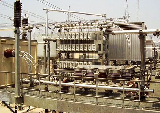
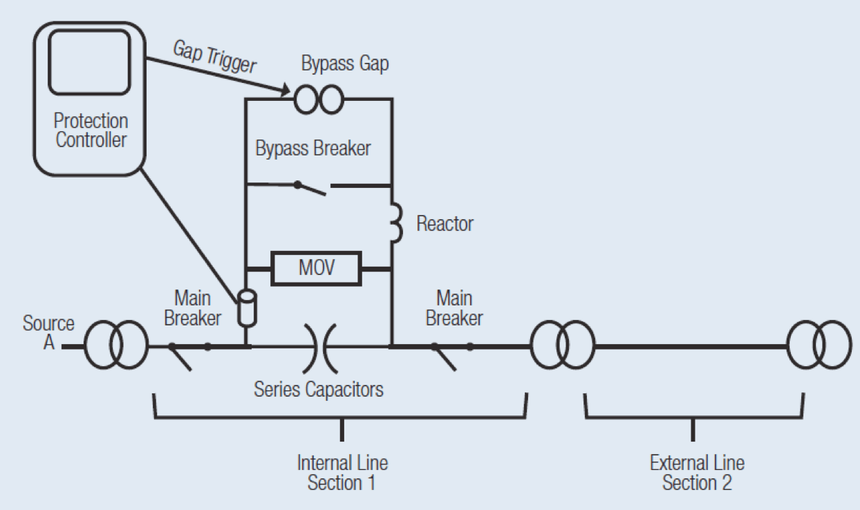
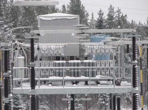
Fig. 1 shows that a series bank is typically mounted on a platform and, while in service, the entire structure above the insulators is energized at system voltage. The series capacitor platform is connected to the control computer using fiber optic links that effectively isolate the protection controls from the high voltage. The typical protective bypass system consists of a metal oxide varistor, bypass gap, damping reactor and bypass circuit breaker. The varistor serves to provide overvoltage protection during power system faults. The bypass gap is then controlled to spark over in the event of excess varistor energy while the bypass breaker closes automatically in the case of prolonged gap conduction or other platform contingencies. The breaker also allows the operator to insert or bypass the series capacitor. The damping reactor limits capacitor discharge resulting from gap sparkover or bypass breaker closure.
[inline_ad_1]
The varistor and the triggered gap operate independently on each phase while the bypass breaker operates on a three-phase basis. The bypass system is capable of operating with single-pole or three-pole tripping and re-closing schemes employed on the transmission lines.
CLICK TO ENLARGE
Protective Role of MOVs
The varistor’s role in protection of capacitors in these applications is simple but also unique. Simple, because the arresters are installed for one purpose only – to limit the voltage across the capacitors during a fault on the system. And unique because, while limiting the voltage during a fault, they also called on to conduct a large portion of the fault current. In fact, there are few other applications where conduction of power frequency fault current is the responsibility of the arrester.
[inline_ad_2]
Conducting fault current for 50-100 ms is much different from normal switching and lightning overvoltage events that are over in a few microseconds to a millisecond. Since the MOVs are connected in parallel with the capacitors at all times, they do not need any special signal to enter the protection scheme. They are always ready and, if there is a fault on the system, the MOV is immediately available to protect.
CLICK TO ENLARGE
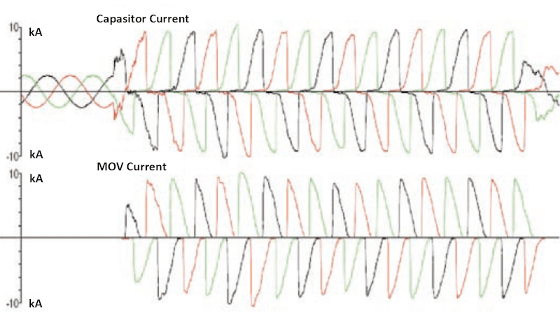
The unusual aspect of this application is that the MOVs are themselves protected by electronic controls as well as the triggered bypass gap. The protection controller monitors current through the MOVs at all times. If at any point the recently-accumulated energy exceeds the rating of the MOV bank, the bypass gap is triggered. This gap is capable of operating and redirecting the fault current away from the MOVs within as little as 1 to 2 ms. Fig. 4 models a three-phase fault and shows the current through the MOV and the capacitors during such an event. Note that the capacitor bank conducts the current for the first half cycle while the MOV conducts the current for the second half. This is due to non-linearity of the MOV.
CLICK TO ENLARGE
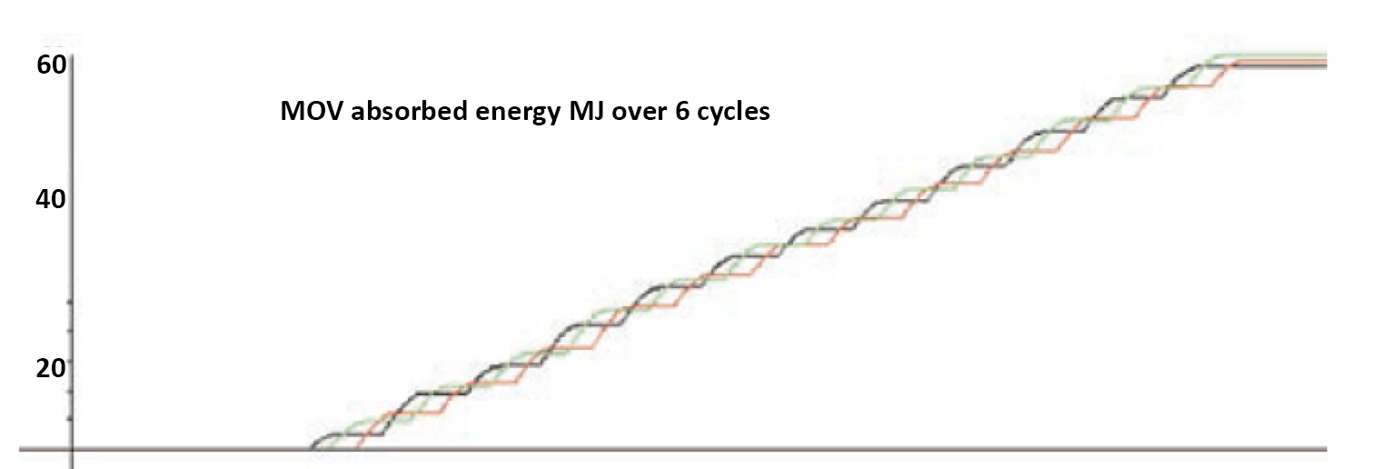
During a fault event, the MOV conduction results in absorption of energy, as shown in Fig. 5. This energy absorption is monitored constantly and forms the basis for triggering the bypass gap.
CLICK TO ENLARGE
There are basically two types of faults of concern for series capacitor installations. If the fault occurs within the section of transmission line where the bank is located, it is referred to as an ‘internal fault’ (see Fig. 3); should a fault occur on another section of line, it is considered an ‘external fault’. The difference between the two lies only in magnitude of the fault. A nearby internal fault will result in significant fault current and significant duty placed on the varistors. A distant fault on an external section can result in a current only a few percent higher than the maximum rated for the capacitor bank. The two types of faults are therefore handled differently by the control system and by the MOVs.
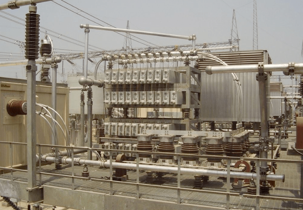
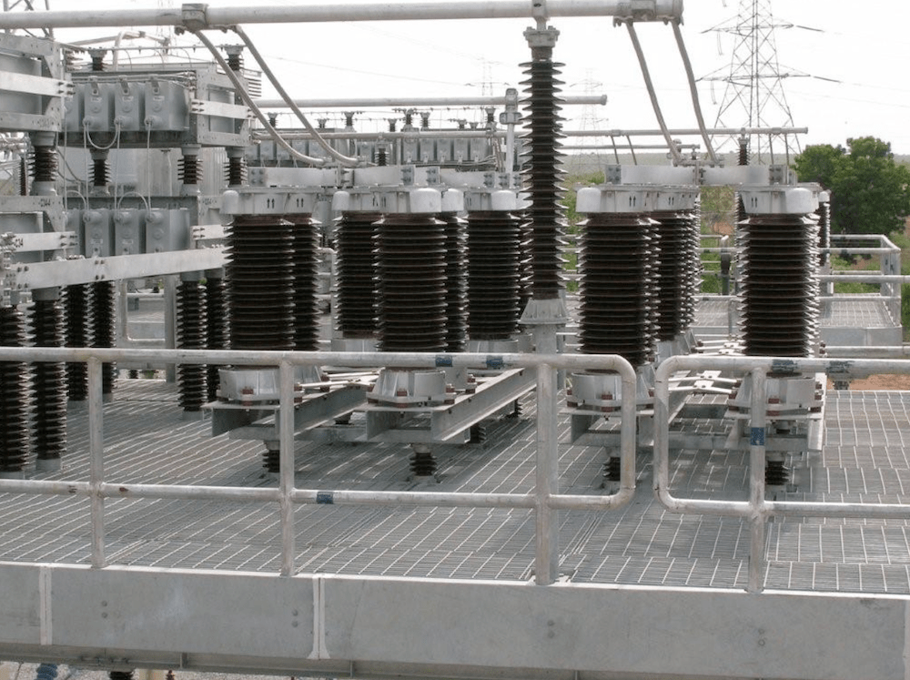
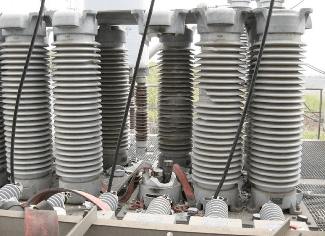
If the control system senses a high current internal fault, it sends a signal to the triggered gap to bypass immediately. This pulls the MOVs out of the circuit before any significant accumulation of energy can take place. When an external fault occurs, the protection controls are all that the MOVs have between operation and overload. If the control system fails, it is likely that the MOVs will as well. To achieve high energy absorption capability, MOV columns are mounted in parallel. For example, Fig. 6 shows a sizable bank of arresters used to protect a series capacitor installation.
CLICK TO ENLARGE
Specifying MOV Banks for Series Compensation Systems
The suppliers of series capacitor banks are generally also the specifiers of all components used in the installation. The characteristics required of the MOV columns are arrived at using an iterative process during a comprehensive system study developed specifically for these applications. This type of study is unique for each installation and is based on the system fault current and operating schemes, as indicated by the end user utility. Size of the MOV bank is a function of many variables and sophisticated models have been developed to speed up and improve the quality of the specification. Once the series capacitor bank supplier has run numerous models and determined the optimum size of the varistor bank, they typically rely on the MOV supplier for the final design and configuration specifications.
Dimensioning MOV Banks
The banks of MOV columns have several critical criteria that need to be met for them to operate properly over the life of the series bank. These characteristics include maximum energy absorption capability, maximum peak current capability, maximum clamping voltage at the highest fault current, minimum re-insertion time, matched ageing characteristics and matched voltage/current (VI) characteristics.
Required Maximum Energy Absorption capability and desired clamping voltage are often the primary factors determining number of columns used in an MOV bank. Based on testing and past performance, the MOV supplier typically will know the maximum energy absorption capability of each disk and column used in this type of application. The energy requirement in this case is much different from standard lightning and switching energy capabilities.
Besides absorbing energy over relatively long periods of time (100 ms vs. 2 ms), the columns are in parallel and share the current according to their design. Maximum energy of the group of parallel columns is a simple sum of the energy absorption of each disk times the energy de-rating factor used in the design.
Matched VI Characteristics or Maximum Current Sharing Deviation is guaranteed by the MOV supplier and is verified in the routine tests performed on all MOV banks. It is also the most demanding task when manufacturing this type of MOV product since it requires painstaking data collection and time-consuming tests to verify and adjust so as to match.
CLICK TO ENLARGE
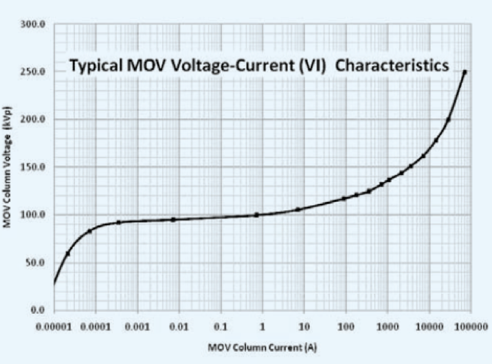
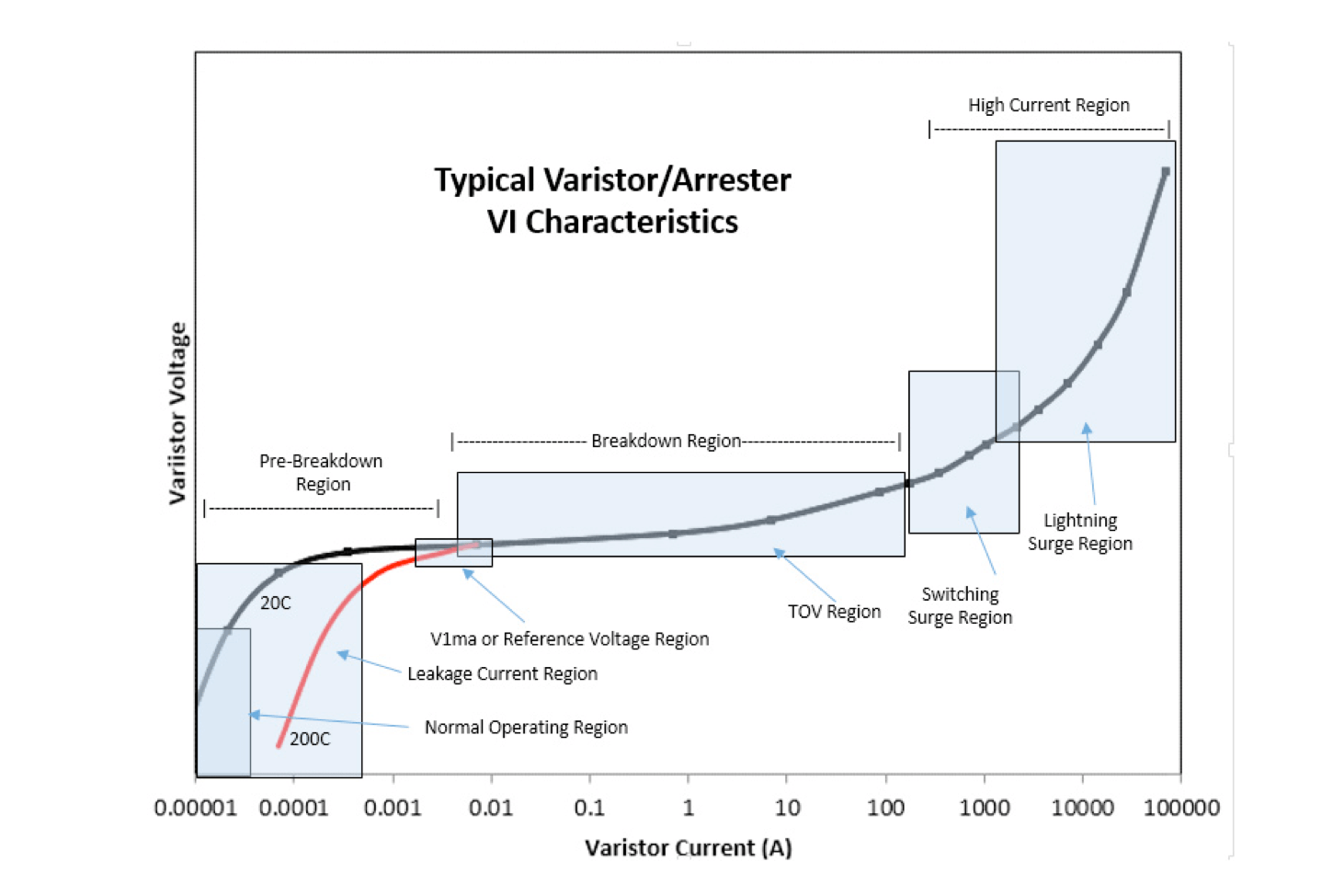
First the VI characteristic of each disk is measured at several points on its VI curve. Fig. 7 provides a typical such VI characteristic of an MOV column and shows the range over which it is important to match it. Above that range, matching is not useful since it is not likely to be a current level the column will ever experience. The area above the critical matching range is in the lightning protection range. The area below the matching range is also not of much importance since current and losses in that region are insignificant and would not lead to any heating imbalance in the bank.
If three points along the VI curve can be matched when assembling an MOV column for this application, the bank will be perfectly matched. If three points between two columns are matched, this guarantees that the routine matching test will succeed. If two points are matched, while it is still possible to succeed in the verification test this is no longer guaranteed. If only one point is matched, success in the test is unlikely. These points are accurately matched using sorting schemes unique to each manufacturer. Once the matched columns are partially assembled, each column is impulsed at a current in the range it will operate and compared to all other columns to which it will be mounted in parallel. If the segment or phase calls for 300 matched columns, the comparative test is then performed on 300 columns.
This routine test is required by IEC and IEEE standards and the results are used to guarantee specified matching characteristics. Because MOV disks and columns are highly non-linear, measuring residual voltage during a comparative test does not produce sufficiently accurate current sharing data – only the current through the column can be used for the comparison. Also, since it is unrealistic to test 300 columns in parallel and measure the current through each simultaneously, usually only 10 to 20 are tested at one time and the groups compared to reference samples. This testing technique is basically common to all manufacturers and yields accurate matching.
[inline_ad_3]
Maximum Peak Current Capability is also well known to MOV suppliers based on historical applications and tests. This characteristic becomes important if the MJ rating of the bank is low but the fault current requirement is high. Once the MOV bank is designed, maximum column current is simply the total maximum fault current divided by the number of columns. If maximum capability of the MOV column is exceeded, the number of parallel columns needs to be increased.
Maximum Clamping Voltage, also known as the protective voltage at maximum fault current, is used to determine maximum protective level of the bank. This value is of course important because it is the fundamental role of the MOV bank. Maximum clamping voltage at maximum fault current must be below the withstand level of the capacitor. Capacitor withstand levels are essentially a function of the insulation and configuration of the capacitor bank. If a capacitor bank is to survive the expected life of the installation, this value must be known and absolutely guaranteed. The maximum protective level of a series capacitor bank is the ratio between peak voltage across the MOVs during a maximum fault event divided by peak value of the voltage across the capacitors at rated continuous current. Typical protective levels fall in the range 2.0 to 2.5.
Minimum Re-insertion Time is an increasingly important characteristic of this application. In fact, it is so important that some utilities have chosen to install redundant banks specifically never to be caught without seried compensation on the system. Besides the transmission line running at a lower maximum power flow, utility revenues are adversely affected if a bank is out of service and system stability is sometimes also lost.
CLICK TO ENLARGE
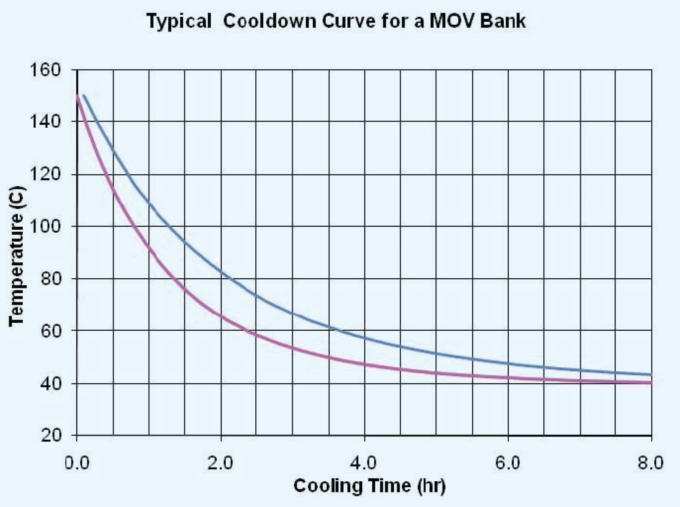
Re-insertion time is a function of the thermal cool down speed of the polymeric-housed MOV column. In Fig. 8, it can be seen that, with a starting temperature of 160°C in an ambient of 40°C, a polymeric-housed MOV column can cool down to within 20°C of ambient in about 4 hours. Since most porcelain MOVs have four columns of disks inside one housing, they generally have a slower cool-down time versus polymeric designs.
Matched Ageing Characteristic is another important characteristic of MOV banks. All MOV material changes over time when energized. These changes are in the low voltage region of the VI curve and therefore do not affect clamping voltage of the column. They can however affect losses or matching characteristics at lower voltages. If one column ages differently from another, it is feasible that current matching and energy sharing can fall out-of-balance. Such imbalance could lead to premature failure of the bank due to overload of one column during a fault. Equal ageing behavior is achieved by the manufacturer using disks with the same impulse and processing history covering the entire segment or parallel group.
Special Testing of MOVs for Series Compensation Systems
IEC standard 60143.2-1994 and IEEE 824-1994 are the two mature and comprehensive standards covering the protective equipment of series capacitor banks. While these standards are not unified, they are similar with both calling out type or design tests as well as acceptance and routine tests. For design tests, all fundamental bank characteristics are covered. Type tests are then carried out on single columns that have been pro-rated from a voltage and current perspective. Required tests consist of residual voltage verification (clamping voltage characteristic), accelerated ageing, current sharing, energy absorption and pressure relief (if requested by the customer). It is important that the energy absorption test be demonstrated for both short-time (sub-cycle) as well as for long-term fault events (5-10 cycles). Longer term fault events stress MOV material differently than any other type of stress encountered in other applications. If there are any inherent defects, such long-term stress can trigger failures in the MOV material that short-term events do not.
Routine Tests
Routine tests are not specifically called out in standards and are left to the discretion of the manufacturer. Still, they need to be robust enough to weed out all defects that could otherwise cause a failure in this unique application. In the case of an arrester used for lightning and switching surges, multiple square wave surges within a short period of time and with sufficient energy level are generally used to verify quality. But for MOV disks used in series capacitor applications, routine tests need to demonstrate both single pulse 8 ms surges and multi-cycle 8 ms pulses since both will be required to protect under these conditions. These energy tests are in addition to the normal residual and Vref tests that must be carried out.
Installation Considerations
Installation configurations are typically a function of platform dimensions, MOV dimensions and clearances as well as metering requirements. It is desirable to use the minimum possible space for the MOV columns so as to allow for reduced platform size. Since MOV columns are always at the same potential as those around them, clearances can be much smaller than during standard arrester applications. A second consideration during installation is to appear as one single MOV, meaning the connecting bus work should be of minimum inductance and resistance. Note the robust bus work on the top and bottom of the arresters in Fig. 6.
Yet another important consideration in mounting MOV columns is metering leakage current in order to monitor their state of health. Of course, since monitoring each column on large banks is not economical, groups of columns are mounted on separate bases. This way, leakage current of one group can be compared to that of an equal group. If these values are noticeably different, inspection is recommended.
[inline_ad_4]
Failure Modes & Considerations
Dealing effectively with failure of a single column has long been a concern for users of MOVs in series capacitor protection. The main issue here is that once the bank is energized it begins ageing. The effect of such ageing is really only an issue if there is a partial failure of the segment. Since the segment is matched from the start and all columns within the MOV bank have aged at the same rate, it is virtually impossible to substitute one column within a group and do so in such a way that current would continue to be shared equally. From the early days of MOV protection of series banks, the solution to this has been to install spares in each bank of columns that are put into service at the same time as the original columns. These so-called ‘hot spares’ see the same fault duty and same voltage profile over the life of the bank. With this solution, should there be a failure in the bank, it becomes a matter of simply extracting the failed column and re-energizing the bank.
CLICK TO ENLARGE
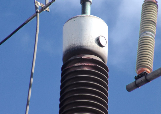
Collateral damage is another concern in the failure mode of large banks of MOV columns (see Fig. 9). For single column, polymer-housed units, any such damage is not expected to be significant and the risk of exceeding the hot spare quantity is not high.
Trends & Conclusions
The utility industry is seeing growing use of series capacitor banks due to the demand for more efficient power transmission and also lower costs. This in turn is driven by the move toward ‘green solutions’ and is a perfect example where, while the product itself may not qualify as ‘green’, its ‘green effect’ can nonetheless be significant. Without MOV columns, series capacitor installations would be considerably more costly and perhaps not even feasible.
A clear trend in this application is conversion of housings to polymers in place of porcelain – a trend also seen in other MOV arrester applications. This move is driven by ease of installation (since rigging equipment is not necessary), by less risk of collateral damage in the event of failure and by the potential to reduce size of banks. In fact, it can be said that porcelain-housed MOV protection for series capacitor banks is now near its end of life.
Wherever there is considerable separation between generation and demand for power, there will be a need for lengthy transmission lines. These lines are then inherently inductive because of the long conductors and this inductive component will need compensation no matter where the line is located – cold climate or hot.
CLICK TO ENLARGE