Dot matrix LED displays are fun. What developer wouldn’t love a blank canvas of lights to play with? I recently paired up a 32 x 16 Dot Matrix Display from Freetronics with Node.js and got it to display black and white PNG images. In this article, I’ll explain how it all works.
A dot matrix LED display (otherwise known just as a dot matrix display or DMD) is a display with a grid of LED lights that you can turn on and off to display text and shapes. Some of them have multiple colors, whilst others are just one single color. The one we’ll use in this demo has just one color, so we’re limited to black and white images. It is important to note – an LED display is quite different to an LCD display. LCDs use fancy light crystals and are used for displays on VCRs, clocks, calculators and so on. I wrote an article a few weeks ago on Displaying Web APIs on an Arduino LCD Using Node.js. Take a look at that if you’d like to compare the two.
This particular demo requires a Freetronics 32×16 Dot Matrix Display, as it relies on the Freetronics DMD library.
Demo code
If you’re keen to grab the code and give it a try yourself, you can find it here on GitHub.
The Freetronics DMD Library
Drawing lines, shapes and text onto our LED dot matrix display is all done via the Freetronics DMD Library. To use it, complete the following steps:
- Download the DMD library from their GitHub repository.
- Copy those files into your
/Arduino/libraries/folder under their own folder name. For me on my Mac, I placed it inside a folder at/Users/username/Documents/Arduino/libraries/DMD-master. - Download the TimerOne library and place it into your
/Arduino/libraries/folder too. e.g. For Mac users,/Users/username/Documents/Arduino/libraries/TimerOne-r11.
Our Arduino Sketch
Most of the functionality for displaying elements on our DMD will happen within our Arduino sketch code. The sketch code will keep an eye out for messages over the serial port and change the display shown based upon those messages.
The sketch begins with our includes and constants. We include SoftwareSerial.h to allow us to access the serial port and define the width and height of our DMD (32×16 in our case). BUFLENGTH stores the number of lights we’ve got, as this is the max size of the message we want to send our Arduino. In our case, it is 32 multiplied by 16 which is 512.
#include <SoftwareSerial.h>
  #define SCREEN_WIDTH 32
  #define SCREEN_HEIGHT 16
  #define BUFLENGTH 512
Next, we have our includes specific to the Freetronics DMD. These should all be available from the files we copied into our Arduino libraries folder earlier.
#include <SPI.h>
  #include <DMD.h>
  #include <TimerOne.h>
Then, we have two constants DISPLAYS_ACROSS and DISPLAYS_DOWN which are used to define how many LED displays we have joined together. I’m going to assume you are in the same situation as me and just have one display, therefore both of these are equal to one. We then pass that into our DMD library, getting it running using DMD dmd().
#define DISPLAYS_ACROSS 1
  #define DISPLAYS_DOWN 1
  DMD dmd(DISPLAYS_ACROSS, DISPLAYS_DOWN);
The next bit of code is included in the DMD samples. This is the function we call to get the DMD library to refresh the display on a set interval. We define that interval a little bit further down.
void ScanDMD() {
    dmd.scanDisplayBySPI();
  }
We then define our last two variables. These two relate to receiving messages via the serial port. First, buf[BUFLENGTH] stores the buffer of serial port messages on which LEDs should be on and off. Second, bufCount will be used to store how many bytes within this buffer are left to read out.
char buf[BUFLENGTH];
  int bufCount;
Our setup() function begins the whole process using our constants and defined libraries. It begins by listening on port 57600 for serial port messages.
void setup() {
    Serial.begin(57600);
Then, we initialize a timer using the TimerOne library we included earlier. We tell it to countdown from four milliseconds. In Freetronics’ examples, they recommend not setting this to more than five milliseconds to avoid flicker on our display.
Timer1.initialize(4000);We then set it to run the ScanDMD() function when our timer expires, which in turn refreshes the display.
Timer1.attachInterrupt(ScanDMD);Finally, in our setup() function, we clear all pixels on the display by passing in true to the dmd.clearScreen() function. If you pass in false to this function, every pixel will turn on!
dmd.clearScreen(true);In our Arduino’s loop() function, we keep an eye out for any messages on the serial port. We watch to see how many bytes are available for reading from the serial port. If there are bytes available, then we have a message streaming through and we run the serialParse() function.
void loop() {
    if (Serial.available() > 0) {
      serialParse();
    }
  }
Inside serialParse(), we set bufCount to -1 to reset the count value. Then, we read in 512 elements from that array (our BUFLENGTH) using Serial.readBytesUntil(). If there is a \n character, it will also stop reading the array. The main aim here is to keep the serial message within the length of our LED light grid.
void serialParse(void) {
    bufCount = -1;
    bufCount = Serial.readBytesUntil('\n', buf, BUFLENGTH);
If we do have a message in our buffer, then we send it through to parseBuffer() which will parse and display it onto our screen.
if (bufCount > 0) {
      String message = String(buf);

      parseBuffer(message);
    }
  }
Within the parseBuffer() function, we start by clearing the screen ready for us to it light up with a new drawing. Then we create an integer of i to keep track of which position in the array we are reading.
We then iterate through each character in our buffer, from left to right via x looping across until the SCREEN_WIDTH, and top to bottom via y looping down until the SCREEN_HEIGHT. This reads out our one dimensional array into the two dimensional display of our DMD. For each character, we check to see whether it is a '1'. If so, then we draw into that LED on the display at x and y. That will be used for the parts of our image that are black. If it is not '1', then we continue to the next position and so on. Eventually, drawing out our entire image.
void parseBuffer(char* buf) {
    dmd.clearScreen(true);

    int i = 0;

    for (byte y = 0; y < SCREEN_HEIGHT; y++) {
      for (byte x = 0; x < SCREEN_WIDTH; x++) {
        if ((char)buf[i] == '1') {
          dmd.drawFilledBox(x, y, x, y, GRAPHICS_NORMAL);
        }
        i++;
      }
    }
  }
That covers how our Arduino works – if we run that code on our Arduino now with our LED attached, it displays nothing at all. To have anything display on our dot matrix display, we need our Node code to send it a message over the serial port.
Our Node Code
Our JavaScript begins by requiring two important npm modules. serialport is what will allow us to send messages via the serial port to our Arduino and png-js is what will read in our PNG images.
var SerialPort = require('serialport').SerialPort,
      PNG = require('png-js'),
We then set up our serial port messaging. We set up a SerialPort object inside the variable serialPort, with settings for which port our Arduino is connected to and which baud rate we’ll be listening for serial port messages on.
serialPort = new SerialPort('/dev/tty.usbmodem1431', {
baudrate: 57600
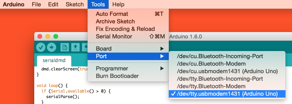
}),If you aren’t sure which port your Arduino is connected to (e.g. I have '/dev/tty.usbmodem1431'), connect it to your PC, open up the Arduino IDE, go to Tools > Port and see which is selected.
The baud rate can be personal preference, if you aren’t really concerned about which baud rate it is using, feel free to stick with the one we’ve already got in the example.
We then initialize a string variable called serialMessage which will store the full string of ones and zeros we’ll send through our serial port.
serialMessage = '';Our serialPort object has an event listener of 'open' which it responds to when the serial port defined is open and ready to access from our JavaScript. When this is the case, we run console.log so we can be certain all is well with our serial port messaging.
serialPort.on('open', function() {
    console.log('Serial port open');
Once we know our serial port is ready for messages, we run the PNG.decode() function to read in our PNG image file. In our demo, we’ve got a PNG image inside the same folder as our Node file called sitepointlogo-withsmile.png, so we pass in that file name. Then we have our callback function which provides us with the PNG file’s data via a data variable.
PNG.decode('sitepointlogo-withsmile.png', function(data) {
    // We'll read in data here
The data returned from our PNG.decode() function will be an array of values from 0 to 255. They iterate through each pixel with a series of four items for each – a red, a green, a blue and an alpha value. We won’t be using the alpha value in our demo as we’re dealing just with black and white images but you theoretically could if you wanted to. A sample array looks like so:
[255,255,255,255,0,0,0,255]The above array represents one white pixel with 255,255,255,255 and one black pixel with 0,0,0,255. This continues over and over for every pixel until we’ve represented the whole image.
Within our callback function, we reset serialMessage to be a blank string and then begin iterating through the data array in sets of four. We set a local variable of red, green and blue to match each pixel’s respective value.
serialMessage = '';

  for (i = 0; i < data.length; i+=4) {
    var red = data[i],
        green = data[i+1],
        blue = data[i+2],
In order to be able to deal with greyscale values that aren’t completely black or white, we’ve also got a luminance check. The function below determines how dark or light the pixel’s color is:
luminance = ((red * 299) + (green * 587) + (blue * 114)) / 1000;If that value is greater than 150, then we’re assuming it’s a pretty light color and setting it to 0 (white). Otherwise, we set it to 1 and make it black. We append either value to the serialMessage string.
if (luminance > 150) {
      serialMessage += '0';
    } else {
      serialMessage += '1';
    }
  }
Once we’ve gone through every pixel and allocated either a zero or a one to represent it, we send that message over the serial port using serialPort.write(). This whole process of reading in an image and iterating through actually seems to be faster than the time it takes for the display to be ready to receive it, so I’ve put it inside of a setTimeout to get it to wait two seconds before running.
setTimeout(function() {
    serialPort.write(serialMessage);
  }, 2000);
Running Our Demo
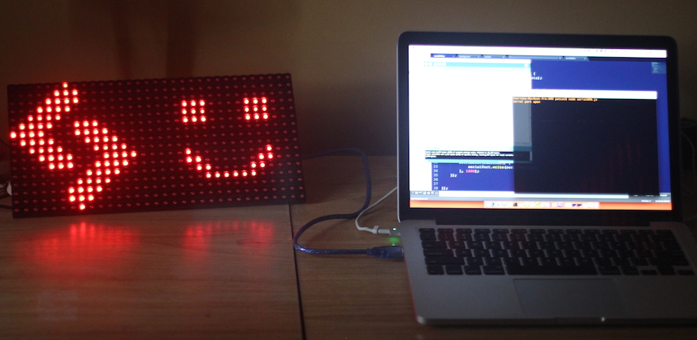
If you upload the sketch, connect the display to your Arduino and run the node server code via node serialDMD.js (remember to npm install everything first), you should see it light up with your PNG file like so:
Conclusion
There are plenty of ways you could expand on this. It is a Node server, so you could hook it up to an API and display images that pass through it. You could make it display a different image depending on time of day, the state of an internet connected device in your home, the weather or any number of other things!
If you expand out this idea into something really neat, let me know in the comments or get in touch with me on Twitter (@thatpatrickguy), I want to see!
Frequently Asked Questions (FAQs) about Displaying Images on a Dot Matrix LED Display with Node.js
What is the Role of Node.js in Displaying Images on a Dot Matrix LED Display?
Node.js plays a crucial role in displaying images on a Dot Matrix LED display. It is a JavaScript runtime built on Chrome’s V8 JavaScript engine, which is used for developing server-side and networking applications. In the context of Dot Matrix LED displays, Node.js is used to control the display and manipulate the images to be shown. It allows for the creation of a server that can send data to the LED display, enabling the display of images, text, or any other data type.
How Can I Connect My Dot Matrix LED Display to My Computer?
Connecting a Dot Matrix LED display to a computer typically involves using a microcontroller, such as an Arduino or Raspberry Pi. The microcontroller acts as an intermediary between the computer and the LED display. You can then use Node.js to send data from your computer to the microcontroller, which then sends the data to the LED display.
Can I Use Other Programming Languages Besides Node.js to Control a Dot Matrix LED Display?
Yes, you can use other programming languages to control a Dot Matrix LED display. While this article focuses on using Node.js due to its ease of use and versatility, other languages like Python, C++, and Java can also be used. The choice of programming language largely depends on your comfort level and the specific requirements of your project.
What are the Advantages of Using a Dot Matrix LED Display?
Dot Matrix LED displays offer several advantages. They are highly versatile and can display text, numbers, and images. They are also energy-efficient, durable, and have a long lifespan. Additionally, they offer high brightness and visibility, making them suitable for various applications, from advertising boards to information displays.
How Can I Display Custom Images on My Dot Matrix LED Display?
Displaying custom images on a Dot Matrix LED display involves converting the image into a format that the display can understand. This typically involves converting the image into a binary format, where each pixel is represented by a 0 (off) or 1 (on). You can then use Node.js to send this binary data to the LED display.
Can I Use Dot Matrix LED Displays for Large Scale Applications?
Yes, Dot Matrix LED displays are suitable for large-scale applications. They can be combined to create larger displays, making them ideal for applications like digital billboards, public information displays, and large-scale advertising.
What is the Lifespan of a Dot Matrix LED Display?
The lifespan of a Dot Matrix LED display can vary depending on the quality of the LEDs used and the conditions in which the display is used. However, LED displays are generally known for their longevity and can last for tens of thousands of hours of use.
How Do I Troubleshoot Issues with My Dot Matrix LED Display?
Troubleshooting issues with a Dot Matrix LED display can involve checking the connections between the display and the microcontroller, ensuring the correct data is being sent to the display, and checking the power supply. If you’re using Node.js, you can also use debugging tools to help identify any issues with your code.
Can I Use Dot Matrix LED Displays Outdoors?
Yes, Dot Matrix LED displays can be used outdoors. However, it’s important to ensure that the display is properly protected from the elements. This can involve using a weatherproof casing or installing the display in a sheltered location.
How Can I Optimize the Brightness of My Dot Matrix LED Display?
The brightness of a Dot Matrix LED display can be controlled using Pulse Width Modulation (PWM). This involves varying the amount of time that each LED is on, which in turn controls the brightness of the display. You can use Node.js to control the PWM signal sent to the LED display, allowing you to adjust the brightness as needed.
 Patrick Catanzariti
PatCat is the founder of Dev Diner, a site that explores developing for emerging tech such as virtual and augmented reality, the Internet of Things, artificial intelligence and wearables. He is a SitePoint contributing editor for emerging tech, an instructor at SitePoint Premium and O'Reilly, a Meta Pioneer and freelance developer who loves every opportunity to tinker with something new in a tech demo.